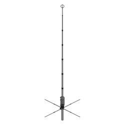
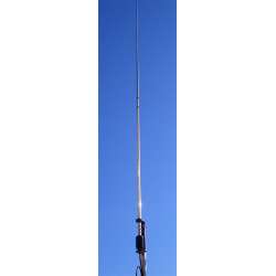
Vertical multiband 1/4 λ Ground Plane base-fed antenna
HF 20, 17, 15, 12, 10m + VHF 6m
Powered at the base
Max Input Power: 3 kW
Total Height: 6,75 m
Antenna weight: 7.8 kg

Security policy

Delivery policy
Main Features
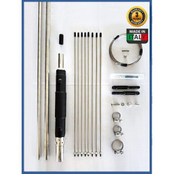
Vertical multiband 1/4 λ Ground Plane base-fed antenna for the following HAM bands: 20, 17, 15 12, 10 and 6m.
Extremely robust construction in AW6063-T66 aluminum alloy and CNC machined parts from solid stock.
Supplied with high-quality 304 and 316 stainless steel fasteners for long rust-free operating life.
High input power, up to 3 kW continuous All-mode.
Detailed assembly manual and serial number that identifies the production batch and construction data.
MATERIALS AND CONSTRUCTION
FFor our tubes, we used the best material that can be used for antenna construction; it is the Aluminum, Magnesium and Silicon alloy named AW6063-T66, hardened to the T-66 state. It gives the stylus exceptional strength, which is made by extrusion and then cold-drawn.
Of extremely robust construction, the central stylus uses 42x2mm diameter tubes at the base and 19x1.25mm diameter at the tip, while the side stubs and ground plane radials are made of 13 and 10mm diameter telescopic tubes;
The ground plane is formed by 4 horizontal radials of approximately 2.7m in length, and the vertical stubs are held in place by 3 crossbars, the first connected to the base of the stylus is made of CNC-machined rectangular-section aluminium tubing, and the other 2 of thermoplastic material, one with 4 arms in the middle part, and one with 2 arms in the upper part.
All hardware is made of stainless steel, the tubes are secured with robust, quality stainless steel AISl-316 clamps, brackets, hardware, and U-bolt and V-bolt U-bolts are made of AISl-304 stainless steel.
Electrical Data
Antenna Type:Ground Plane 1/4 λ with parallel stubs
Frequency Range: HF 20, 17, 15, 12, 10 + VHF 6m
Impedance: 50Ω Unbalanced
Radiation Type: Omnidirectional
Polarization: Linear – Vertical
Gain: 0 dBd – 2,15 dBi
Bandwidth SWR 2: ≥ 20, 17, 15, 12 full band 10&6m > 1.5:1
SWR @resonance: ≤1.5:1 (Typical)
Max. Input Power: 3000 Watts continuos all mode
Feed system: Direct - connected to DC ground
Input connector: 50Ω UHF female PTFE insulator, gold plated pin
Mechanical Data
Materials: Aluminnum Alloy AW6063-T66 hard drawn tube, Fiberglass, Brass, PTFE. All hardware are made of SS AISI-304 and 316
Wind surface area: 0,4m2
Wind survival (no ice): 130 km/h (braked)
Total height: 6.75m
Whip length: 6.20m
Radial length: 2.7m
Mounting mast bracket: ø 40-54 mm
Antenna Net weight: 7.8 Kg
Package dimensions: 14x14x145 cm
Weight in package: 9,1Kg
A high-performance and robust antenna with Grazioli brand standards.
The basic idea was to make an efficient antenna, without using traps that reduce efficiency, and without using impedance transformers that limit the applicable power.
Based on these assumptions, we realised MV6, which by using resonant elements parallel (stubs) to the central stylus, allowed us to realise an efficient antenna on all bands covered.
A high-performance multiband
The stylus consists of a central radiator for the lower 20m band flanked by 4 side stubs resonating on the higher 17,15,12,10 + VHF 6m bands. The side stubs are 1/4 wavelength without traps that would reduce their efficiency. The antenna is fed directly without the use of impedance adapters or transformers, which would introduce losses and limit the applicable power, and is equipped with a high-impedance inductance that creates a DC short circuit, grounding any disturbances caused by atmospheric events and/or electrostatic discharges.
Calibration is done by adjusting the telescoping parts of the stubs and the central stylus, each frequency is independent and does not affect the other bands, except for the 17m band, which also determines the resonance of the 6m band: We recommend the use of a graphic antenna analyser such as Rig-Expert or Nano VNA, which makes calibration much easier.
NOTE:
If used in very windy areas, bracing with non-conductive cables using the supplied fifth wheel is recommended.
We recommend the use of a CHOKE (not supplied) to be installed immediately below the connector to avoid possible RF feedback on the coax
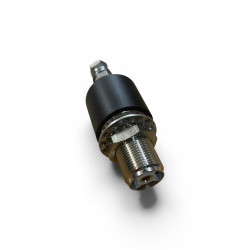
UHF Connector
The FE10V connector is not a commercial SO-239 type connector as most manufacturers use. The connector was designed and built directly by us, has a real impedance of 50 Ohms and can be used up to 500 MHz. The goal was to create a reliable connector capable of withstanding 5kW CW continuous at 30 MHz.
The body is made of CW614N nickel-plated brass, while the pin is plated in 24K gold to avoid oxidation and equipped with a 4-fin insulator that maintains its centering and elasticity, avoiding contact losses.
The insulating part is made of PTFE which is one of the best insulating materials due to its exceptional electrical (low dielectric constant, and reduced loss factor) and thermal (operating temperature from -100 ° to + 260 °) and is protected from a special elastomer hood that prevents water and humidity infiltration
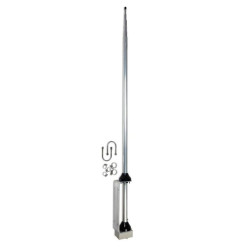
The fixing bracket
Made of 2.5mm thick AISI304 stainless steel, it is fixed to the antenna tube by means of a clamp closure system, creating an extremely strong mechanical locking.
Fixing to the mast is made with AISI304 M6 V-Bolt and high type nuts to facilitate tightening.

Associated Products
Vertical multiband 1/4 λ Ground Plane base-fed antenna
HF 20, 17, 15, 12, 10m + VHF 6m
Powered at the base
Max Input Power: 3 kW
Total Height: 6,75 m
Antenna weight: 7.8 kg