Security policy

Delivery policy
Main Features
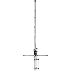
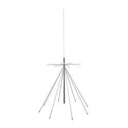
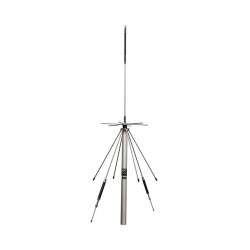
Vertical 2x5/8 λ collinear VHF antenna. Adjustable from 50 to 54 MHz with tuning table.
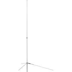
Antenna also configurable in short 5/8 λ version with whip length adjustment chart.
Extremely robust construction in AW6063-T66 aluminium alloy.
Supplied with high-quality 304 and 316 stainless steel fasteners for long rust-free operating life.
The Ground plane consists of four full quarter-wave radials.
High input power, up to 2 kW continuous all-mode.
Detailed assembly manual and serial number that identifies the production batch and construction data.
Materials and Construction
For our tubes, we have used the best antenna construction alloy available: AW6063-T66 is an alloy of Aluminium, Magnesium and Silicon that is hardened to a T-66 temper which gives the stylus exceptional resistance. It is shaped by extrusion and subsequent cold drawing. Our tubes are extremely accurate on both diameters and also on the wall thickness, ensuring a precise fit with less ‘play’ between the tubes.
The "Ground Plane" is composed of four robust full-quarter wave radials with a length of 1,4 m. Each radial is a single-section tube with a diameter of 13 mm and wall thickness of 1,25 mm, fixed to the support plate by means of two U-bolts and self-locking nuts, in the fixing area. Four glass fibre reinforcements are provided to strengthen the joints and prevent the pipes from being crushed.
Technical Data
Electrical Data Mechanical Data
Antenna Type 2x5/8 λ Collinear Ground Plane with four radials Materials Aluminium Alloy AW6063-T66 hard drawn tube, Fiberglass, Brass, PTFE. All hardware are made of SS AISI-304 and AISI316
Frequency range Tunable from 50 to 54 MHz Wind surface area
0,195m2 / 2,1 ft2
Impedance 50Ω Unbalanced Wind load @ 130Km/h /80Mph 19 Kgf / 42 lbs
Radiation (H Plane) Omnidirectional Wind survival (no ice) 130 Km/h
Radiation (E Plane) Beamwidth @ -3dB = 30° Overall Antenna height 8,12 m / 26,6 ft @ 50MHz
Polarization Linear – Vertical Radiator length 7,6 m / 24,9 ft @ 50MHz
Gain 3,5dBd – 5.65dBi Radials length 1,4 m / 4,6 ft (Full quarter wave)
Bandwidth @SWR 2:1 ≥ 2.6 MHz @ 50MHz Mounting mast bracket ø 40-54 mm / ø 1,57" to 2-1/8"
SWR @resonance ≤1.2:1 @ typical <1.1:1 Antenna weight 4,3 Kg / 9,5 lbs
Max. Input Power 2000 Watts continuos all mode Package dimensions 14x14x145 cm
Feed system High “Q” air wound matching coil, DC-Ground Weight in pack 5,4Kg
Input connector 50Ω UHF female PTFE insulator, gold plated pin
The technical solutions that make the difference
Why build an antenna capable of withstanding 2kW of continuous power?
Because an antenna that accepts high power is a more efficient antenna. Otherwise, it would tend to heat up due to the Joule effect and dissipate a significant part of the applied RF power as heat, something that happens with most competing products but which, unfortunately, users cannot test for want of adequate equipment and instrumentation.
The high-"Q" coil
The coil plays a key role in impedance matching and maximum RF power transfer.
Q, the Quality Factor, is determined by its length/diameter ratio, the pitch between the turns, the material, the diameter of the wire and the presence or absence of metal cores.
In simple terms, the higher the Q of the coil, the lower the high frequency losses.
We have created a generously sized coil suspended in air without metal cores, with widely spaced turns obtaining one of the highest Q values technically possible.
This ensures maximum efficiency and the ability to withstand high RF power levels.
In addition, the coil is directly dc-grounded to ensure that atmospheric disturbances and background noise are significantly reduced.
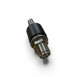
UHF Connector
The antenna connector is not the commercial SO-239 type used by most manufacturers. Our connector is designed and built directly by ourselves; it has a true 50 Ohm characteristic impedance and is rated up to 500 MHz.
We have created a reliable connector capable of withstanding 2 kW of continuous RF power at 30 MHz and greater than 3 kW at 50 MHz.
The body is made of CW614N nickel-plated brass, while the pin is plated in 24K gold to avoid oxidation and is equipped with a 4-fin insulator that maintains its centring and elasticity to avoiding contact losses.
The insulating material is PTFE, one of the best insulators due to its exceptional electrical and thermal properties (low dielectric constant and reduced loss factor, operating temperature from -100 to +260 °C). The entire assembly is protected by a special elastomer hood that prevents water and humidity infiltration
Anchor bracket
Made of 2.5 mm-thick AISI 304 stainless steel, it is attached to the antenna tube by means of a clamping system, creating an extremely robust mechanical lock.
The mast coupler is consists of an M6 V-Bolt in AISI 304 steel and column nuts for easy, secure tightening.

Associated Products