- Out-of-Stock


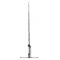
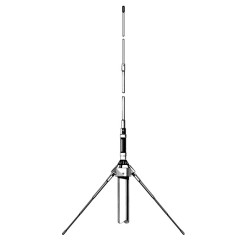
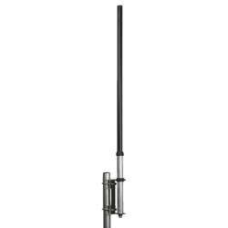
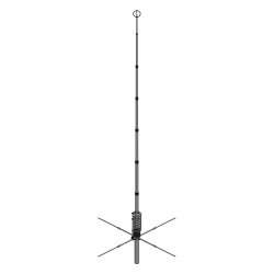
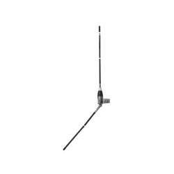
Vertical Antenna 5/8 λ
Tunable from 26 to 30 MHz
Powered at the base
Max Input Power: 5 kW
Total Height : 7,63 m
Antenna Weight : 6 Kg

Security policy

Delivery policy
Main Features
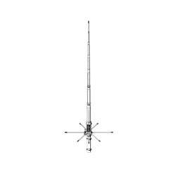
Grazioli FE10V is a 5/8 λ antenna for the 10 or 11m band.
Extremely robust, performing antenna with a low angle of radiation, and that could withstand extremely high powers (5kW CW continuous all-mode).
The result is FE10V which has unique characteristics in the current market and collects all our experience in this field.
MATERIALS AND CONSTRUCTION
For our tubes we have used the best alloy that can be used for the construction of the antennas the AW6063-T66 alloy of Aluminum, Magnesium and Silicon hardened to the T-66 state which gives the whip an exceptional resistance, which is made by extrusion and subsequently cold drawn.
Our tubes are extremely precise on both diameters, and also on the thickness of the wall, allowing a precise coupling and with less “play” between the tubes.
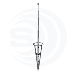
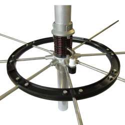
The “Ground Plane” is composed of 4 robust radials with a length of 2.7m, “Full-Quarter Wave” made in two telescopic sections with clamp fixing, with a diameter and wall thickness respectively 13 × 1.25mm and 10x1mm, which are fixed to the support plate by means of two U-Bolt and self-locking SS nuts.
4 glass fiber reinforcements are provided in the fixing area which strengthen the joints and avoid crushing of the pipes.
Electrical Data
Antenna Type:5/8 λ GP with 4 full ¼ d’wave radials
Frequency Range: Tunable from 26 to 30 MHz (with Graph)
Impedance: 50Ω Unbalanced
Radiation Type: Omnidirectional
Polarization: Linear – Vertical
Gain: 1,5dBd – 3.65dBi
Bandwidth @SWR 2:1: ≥ 1.4MHz @ 26MHz to ≥ 1.6MHz @ 30MHz
SWR @resonance: ≤1.2:1 @ antenna connector
Max. Input Power: 5000 Watts continuos all mode
Feed system: high-Q air wound matching coil, DC-Ground
Input connector: 50Ω UHF female PTFE insulator, gold plated pin
Mechanical Data
Materials: Aluminnum Alloy AW6063-T66 hard drawn tube, Fiberglass, Brass, PTFE. All hardware are made of SS AISI-304 and 316
Wind surface area: 0,29m2
Wind load @ 130Km/h: 280N – 28,5Kgf
Wind survival (no ice): 130 Km/h
Antenna Height: 7.63m a 26MHz
Radials length: 2,7m (Full quarter wave)
Mounting mast bracket: ø 40-54 mm
Antenna Net weight: 6 Kg
Package dimensions: 14x14x145 cm
Weight in package: 7,3Kg
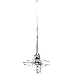
The RESONANT "Full-Quarter Wave" Ground Plane
From our electromagnetic simulations also validated by comparative instrumental tests, with this ground plane which is widely used for most antennas (from the HF to UHF bands) the performance in terms of horizontal angle of maximum radiation or Take-Off is considerably better.
We compared two identical 5/8 antennas, one with a GP consisting of 8 NON-RESONANT radials of 1/8 lambda (about 1.35m long), and one with a GP of 4 RESONANT radials of ¼ lambda (about 2.7m long) under the same installation conditions.
The result of our test is that the version with 4 resonant radials ¼ lambda always obtains a maximum radiation angle or take-off of about 4 ° or 5 ° lower, allowing a considerable improvement of long distance DX connections.
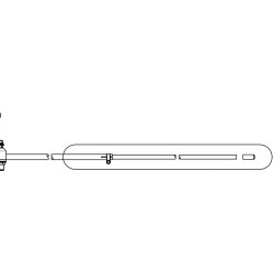
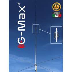
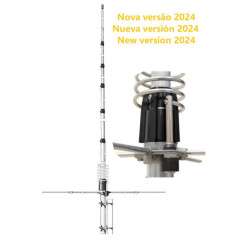
The high “Q” Coil
The coil plays a fundamental role for impedance matching and maximum RF transfer, its shape given by the length / diameter ratio, the pitch between turns, the material and diameter of the wire and the presence or absence of metal cores within it, determine the quality factor “Q”.
In simple terms, the higher is the “Q” value of the coil, the lower is the losses at high frequency.
We have created a generously sized coil suspended in the air without metal cores, with an L / D ratio of 1.3 and widely spaced turns, obtaining a “Q” value of about 2500 at a frequency of 28MHz, when the best competing antennas do not reach 1500.
This translates into maximum efficiency, and the ability to withstand high RF powers.
In addition, the coil is directly connected to ground in direct current (DC-Ground), in this way atmospheric disturbances and background noises are significantly reduced.
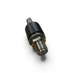
UHF Connector
The FE10V connector is not a commercial SO-239 type connector as most manufacturers use. The connector was designed and built directly by us, has a real impedance of 50 Ohms and can be used up to 500 MHz. The goal was to create a reliable connector capable of withstanding 5kW CW continuous at 30 MHz.
The body is made of CW614N nickel-plated brass, while the pin is plated in 24K gold to avoid oxidation and equipped with a 4-fin insulator that maintains its centering and elasticity, avoiding contact losses.
The insulating part is made of PTFE which is one of the best insulating materials due to its exceptional electrical (low dielectric constant, and reduced loss factor) and thermal (operating temperature from -100 ° to + 260 °) and is protected from a special elastomer hood that prevents water and humidity infiltration
The fixing bracket
Made of 2.5mm thick AISI304 stainless steel, it is fixed to the antenna tube by means of a clamp closure system, creating an extremely strong mechanical locking.
Fixing to the mast is made with AISI304 M6 V-Bolt and high type nuts to facilitate tightening.

Associated Products
Vertical Antenna 5/8 λ
Tunable from 26 to 30 MHz
Powered at the base
Max Input Power: 5 kW
Total Height : 7,63 m
Antenna Weight : 6 Kg