• New
DXpatrol QO-100 12 W 2.4 GHz Power Amplifier
search
  • DXpatrol QO-100 12 W 2.4 GHz Power Amplifier
  • DXpatrol QO-100 12 W 2.4 GHz Power Amplifier
  • DXpatrol QO-100 12 W 2.4 GHz Power Amplifier
  • DXpatrol QO-100 12 W 2.4 GHz Power Amplifier
  • DXpatrol QO-100 12 W 2.4 GHz Power Amplifier
  • DXpatrol QO-100 12 W 2.4 GHz Power Amplifier

DXpatrol QO-100 12 W 2.4 GHz Power Amplifier with 12–28 V Converter

€180.00

LDMOS amplifier for transmission in the 2.4 GHz band, specifically designed for the QO-100 satellite uplink. It delivers up to 12 W at 28 V, supports VOX/PTT control, provides power and SWR monitoring outputs and includes a 12-to-28 V step-up converter.

Quantity


Security policy


Delivery policy

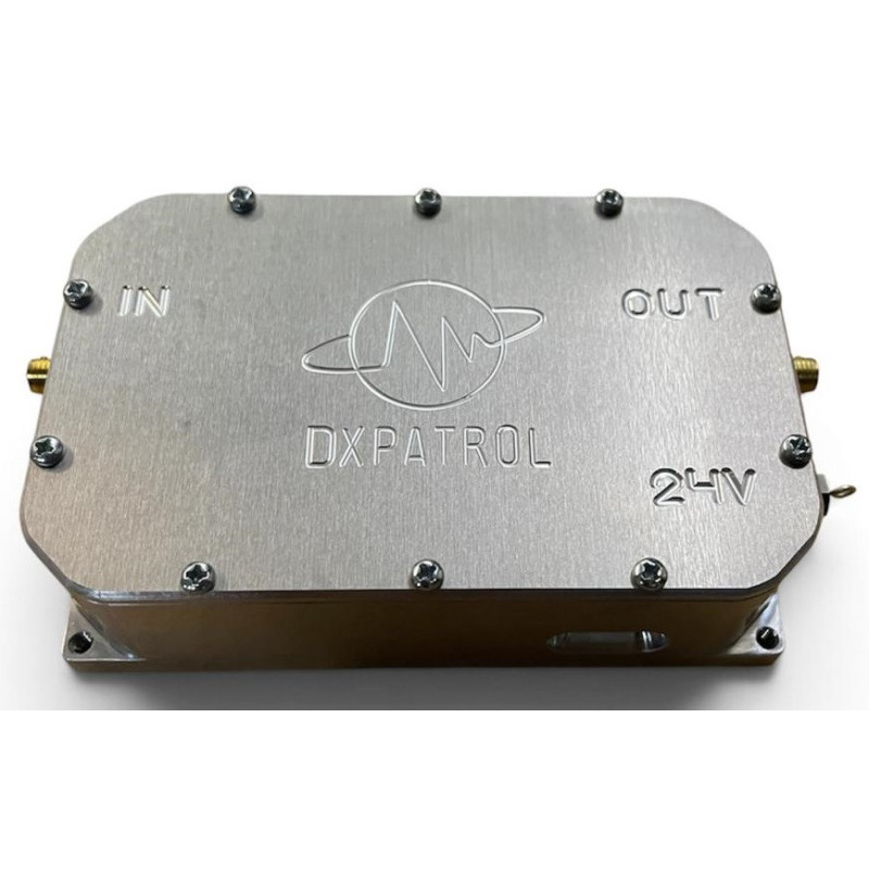
The DXpatrol QO-100 Power Amplifier is a linear 13 cm band power amplifier designed to increase the output signal from an upconverter before transmission through the QO-100 geostationary satellite.

It uses an NXP MHT1008NT1 LDMOS module with an RF2126 driver, providing approximately 24 to 25 dB of gain. With approximately 70 mW of drive power, it can deliver up to 12 W of RF output when powered at 28 V.

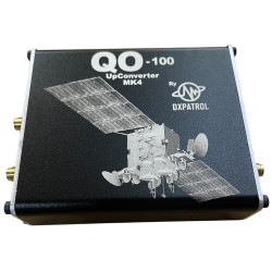
The amplifier is specifically designed to operate with the DXpatrol UpConverter MK4, whose output level is suitable for driving this unit.

Automatic switching is available through RF VOX, while an external ground-activated PTT connection can also be used. Analogue outputs are provided for monitoring forward power and reflected power/SWR through an external measurement system.

The amplifier is housed in a rugged aluminium enclosure and includes a step-up converter that generates the required 28 V supply from a 12 V source.

Main features

  • 2400 MHz RF power amplifier
  • Specifically designed for QO-100
  • Maximum output power of 12 W at 28 V
  • Approximately 5 W with a direct 12 V supply
  • Recommended drive level of approximately 70 mW
  • Approximately 24 to 25 dB gain
  • LDMOS technology
  • Automatic RF VOX switching
  • External ground-activated PTT control
  • Forward power and SWR monitoring outputs
  • 50 Ω RF input and output
  • SMA RF connectors
  • Rugged aluminium enclosure
  • 12-to-28 V step-up converter included

Technical specifications

  • Brand: DXpatrol
  • Type: RF power amplifier
  • Application: QO-100 satellite uplink
  • Band: 13 cm
  • Nominal frequency: 2400 MHz
  • Output power: up to 12 W at 28 V
  • Output power at 12 V: approximately 5 W
  • Recommended drive power: approximately 70 mW
  • Gain: approximately 24–25 dB
  • Impedance: 50 Ω
  • Input SWR: approximately 1.3:1
  • Stated maximum output VSWR: 5:1
  • LDMOS transistor: NXP MHT1008NT1
  • RF driver: RF2126
  • Bias current: approximately 600 mA
  • Maximum current at 28 V: approximately 1.5 A
  • Supply voltage for full output: 28 V DC
  • Included converter: 12 V to 28 V
  • Transmit control: RF VOX or ground-activated PTT
  • Forward power monitor output: 0 to 4 V DC
  • SWR monitor output: approximately 1.5 to 4 V DC
  • RF connectors: SMA
  • Operating temperature: -40 to +80 °C
  • Maximum LDMOS temperature: 150 °C
  • Approximate dimensions: 97 × 62 × 26 mm
  • Mounting threads: M3
  • Enclosure: aluminium

Connections and controls

  • RF IN: input from the upconverter
  • RF OUT: amplified output to the antenna
  • PTT: transmit activation by connection to ground
  • RF VOX: automatic activation when RF is detected
  • PWR/FWD: analogue forward-power monitor output
  • SWR/REF: analogue reflected-power or SWR monitor output
  • 28 V: amplifier power input

Recommended applications

  • Transmission through the QO-100 satellite
  • 13 cm amateur radio stations
  • Amplifying the DXpatrol UpConverter MK4 output
  • 2.4 GHz uplink systems
  • Fixed or portable stations
  • SSB, CW and authorised digital-mode operation
  • Experimental microwave projects

Package contents

  • 1 DXpatrol QO-100 power amplifier
  • 1 step-up converter from 12 to 28 V

Important note

Despite its aluminium enclosure, the amplifier must be installed on a suitable heatsink, particularly for extended transmissions. Inadequate cooling may cause overheating and permanent damage.

Use a regulated power supply with sufficient current capacity. When the step-up converter is used, the current drawn from the 12 V source will be higher than the amplifier current at 28 V.

Do not exceed the recommended drive power. Always verify correct antenna matching and use cables and connectors suitable for 2.4 GHz.

The PWR and SWR connections provide analogue voltages for an external measurement system; the amplifier does not include a standalone display or meter.

The power supply, heatsink, upconverter, meter, cables and antenna are not stated as included.

130101
New